Product Data Management (PDM)
Designed for the collection and organization of files across various design and production phases for a finished product. From the finished product list, select the desired line and the PDM option.

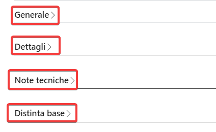
The form is divided into the following sections:
- General
- Details
- Technical Notes
- [Bill of Materials]
- Operations
- Samples
- Compositions
- Model Measurements
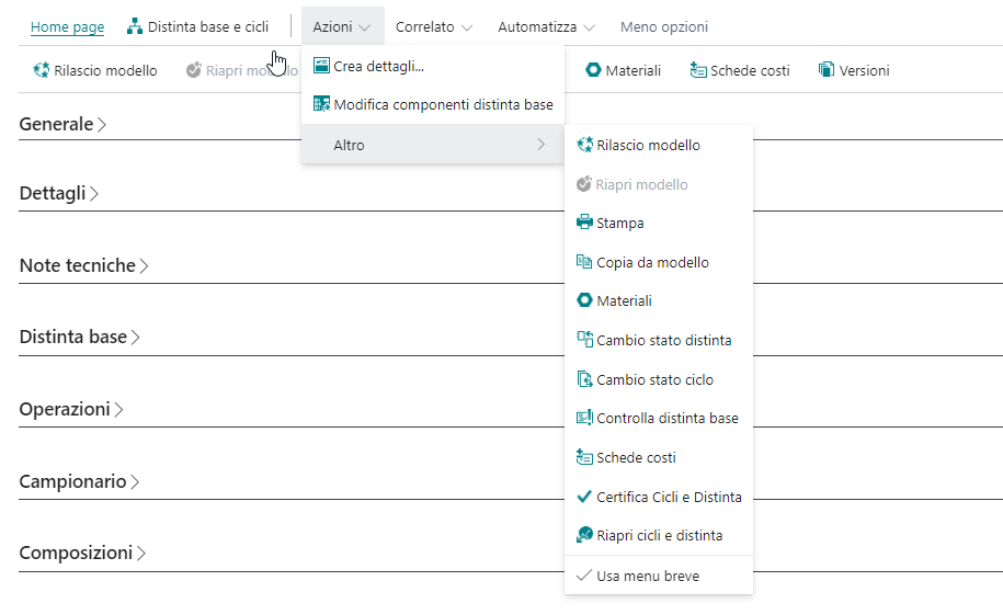
Within PDM, numerous processes can be accessed. Below is the list of available actions.
On the right side of the form, a section contains the attribute tree, displaying the model, materials, colors, and related sizes in which the finished product is developed (the attribute tree will be populated with all dimensions defined in the system setup).
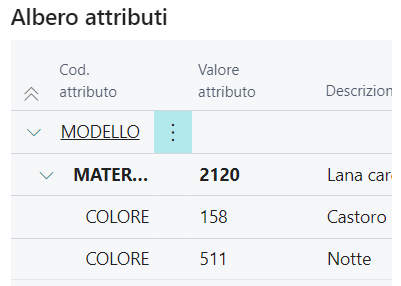
The attribute tree is used to select at which level the various sections comprising the PDM are entered.
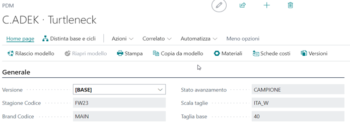
General
Some default data from the finished product master data is displayed.
Details
Data specified and displayed (already present in the model master data) at the material or color level (each fabric will have its own detail or attribute).
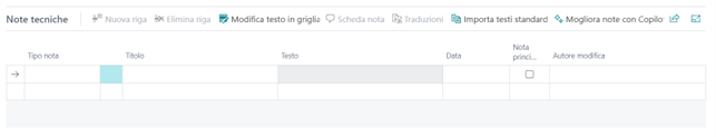
Technical Notes
The "Technical Note" is a note entered at the location of the cursor in the attribute tree, either on the model, a specific material, or a specific material-color combination. Each branch of the tree can have multiple notes, each with a title, description, note type (chosen from the predefined options), date, main note identifier (for printing purposes), and an image.
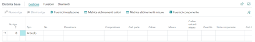
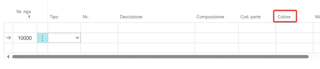
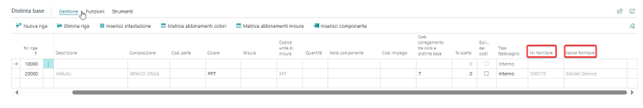
Bill of Materials
This section includes the list of components required to create the finished product. The component list can be defined by model, material, color, or size based on the selection made on the attribute tree.
Matrix rows can take different values; below are the various types:
- Description: A descriptive row is entered for a component not yet coded in the master data, specifying unit of measure and consumption.
- Item: A particular item from the master data is selected.
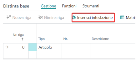
- Header: A descriptive row needed to specify and organize components in the bill of materials.
The header is entered from this button:
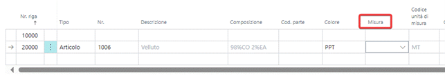
For each bill of materials row entered, a series of information can be specified, including:
- Color: Indicates the component color. For more details on color matching, refer to color matching management.
- Size: Indicates the component size. For more details on size matching, refer to size matching management.
- Link code between routing and BOM: Indicates a code to link the material to the production routing.
- Excluded from costs: Flag indicating whether to include the component in cost calculations.
- Demand type: Indicates the type of demand, which can be:
- Internal: The component is purchased by the company and included in internal demand calculations.
- External: The component must be purchased from the routing supplier and is not included in internal demand calculations.
- Brokerage: The component is negotiated by the company but then purchased by the routing supplier, and thus not included in internal demand calculations.
- None: The component is not included in internal demand calculations.
- Supplier: Supplier code for the component. It is inherited for coded components and can be entered for uncoded materials.
- Attributes: Derived from the attribute tree, in our case, they are color and size, but other desired attributes can be chosen.
Color Matching Management
If the component added to the BOM is color-managed, it is necessary to "match" the color attribute to the corresponding attribute of the finished product.
There are three ways to manage color matching:
- Specify a component color for all finished product colors (see case 1).
- Specify that the component color codes match those coded on the finished product (see case 2).
- Define the corresponding component color for each finished product color (see case 3).
Single Component Color
Specify the color in the BOM section as shown:
Component Color Matching FP
Entering an asterisk in the color column on the row of the component to be matched will automatically load the material colors onto the finished product with matching codes.
Color in Matching
To match colors of the component with different attributes or in contrast to the finished product, activate the matching matrix functionality from the BOM section.
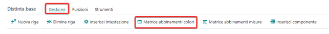
For details on the functionality, refer to matching matrix.
Size Matching Management
If the component added to the BOM is size-managed, it is necessary to "match" the size attribute to the finished product size.
There are three ways to manage size matching:
- Specify a component size for all finished product sizes (see case 1).
- Specify that the component size codes match the sizes coded on the finished product (see case 2).
- Define the corresponding component size for each finished product size (see case 3).
Single Component Size
Specify the size in the BOM section as shown.
Component Size Matching FP
Entering an asterisk in the size column on the row of the component to be matched will automatically load the material attributes onto the finished product with matching codes.
Size in Matching
To match the sizes of the component with those of the finished product, activate the matching matrix functionality from the BOM section:
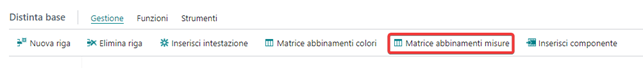
For details on the functionality, refer to matching matrix.
Operations
This section specifies the various processing phases necessary to create the finished product. Production Areas or Work Centers can be entered, where production area refers to the subcontractor or department completing the specified operations, and work center refers to the specific machine dedicated to that activity.
The main tables involved in compiling this section are:
- Type: Production Areas.
- Standard Task.
- Link code between BOM and routing.
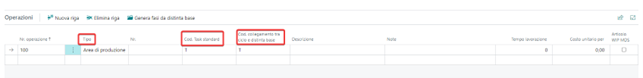
The link code between routing and BOM column allows each processing phase to be linked to the list of components needed for the planned activity. The link code must also appear in the BOM section. The link code value on the BOM line is inherited from the component master data and can be modified manually when defining components.
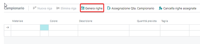
Samples
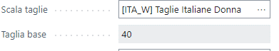
In the Model Sample section, all combinations of finished products to be launched as samples are entered. Using the generate lines function, a line is proposed for each color developed on the base size present in the finished product. Other color-size combinations can also be manually entered or the proposed ones can be modified.
Below is the "base size" field in finished product master data.
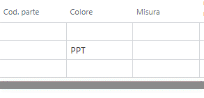
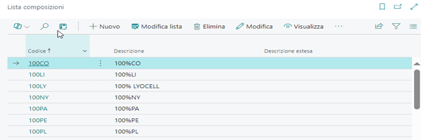
Compositions
This section specifies compositions divided by part code, where part code refers to the breakdown of the finished product into its components.
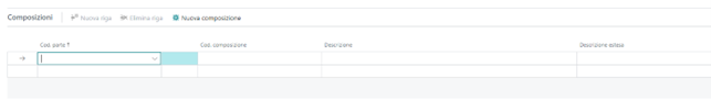
To enter the composition, first populate the part codes table and the composition list table (found in search), and then select the necessary combination.
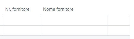
Suppliers
In the bill of materials section, the suppliers listed in the master data for coded components are shown. For uncoded materials, the SUPPLIER No. can be entered manually.
Model Measurements
This includes a list of the different measurement tables that can be associated with the finished product.

For each measurement group, the set of measurements deviating from the base size is defined. For each measurement group, the measurement type to be performed can be defined and tabulated. This way, the minimum tolerance points for shrinkage/increase defined for creating the finished product are established.
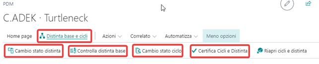
Available Actions
Release model and Reopen model: Certify the model by generating individual SKUs.
Comments: Allows comments and notes to be entered, which will be managed and used in the functions specified during configuration (found under "related").
In the "Bill of Materials and Routings" section:
Change BOM status: Confirms and certifies the BOM components entered in PDM, generating the list of materials needed for each SKU to create the item.
Change routing status: Confirms and certifies the production cycles entered in PDM, generating the necessary production phases for each SKU to create the item.
Check BOM: Performs a formal check of the bill of materials, to be used before change BOM status.
Certify BOM and routings: Certifies the components and production cycles entered to create the item.
Matching Matrix
The matching matrix page (found in the bill of materials) is used to match the component attributes present in PDM with the configured attributes in the finished product.
It is divided into:
- Color matching matrix
- Size matching matrix
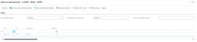
Attribute matching selections are made from the dropdown menu at the top of the matrix (in the filter section), where Parent Attribute Code refers to the finished product attribute, and Component Attribute Code to the material attribute to match. In the filter section, it is possible to reduce the number of displayed columns by appropriately filling the Parent Attribute Code Filter field.
Based on the choices made in the filter section, the component grid will populate with materials to match. From the proposed matrix, select component attributes in the corresponding column of the finished product attribute. The grid will already be populated and not editable for components whose material attribute value has been previously chosen to match that of the finished product. Matched components with the same code are highlighted in bold.
Additionally, it is possible to exclude one or more material components from matrix matching. To exclude a specific cell, enter a dash ("-") in the desired cell. In this case, the corresponding material will be excluded from the list of components required to create the finished product. Highlighted attributes will not be considered during BOM release.
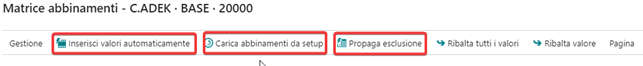
There are additional functionalities on the matching matrix page that facilitate the attribute association of the component with the finished product attribute.
Insert values automatically: Automatically fills the matching cells with the value from the previous component cell. Filling in highlighted values and selecting the "insert values automatically" action will populate unhighlighted cells with the data from the preceding cell.
Load matching from setup: Allows pre-setting the standard component matching before completing the matrix by properly filling in the Model Matching Setup List table, and then applying it automatically.
Exclude propagation: Inserts the exclusion from matching value into all empty cells, allowing the matching to be completed by excluding unfilled cells.
